HydroFan - Pico Water Power (part 1)
Jeff Davis,December 2, 2006
This is a concept model of a water powered stove fan called the HydroFan. The goal of this design is to provide a powered fan for cook stoves which is powered by a few gallons of water placed above, in a container, and to the side of the stove. The water would flow through a tube setting a water wheel in motion. This water wheel would be coaxial with a fan which ultimately provides the stove with forced draft via duct work leading to the stove. The water would be collected by a shroud and drain into a container resting on the floor. Later this water would be emptied into the top container for later use. Possibly a valve like device could be used to vary the RPMs of the fan.
In other words, this is a gravitational battery and motor pico prime move. Frankly, I'm skeptical in regards to battery powered fanned stoves. What about people that can not afford this type of technology or what if something happens in the world that prevents all people from having batteries, motors and solar cells for recharging.
In the future, I plan to investigate the possibilities of applying HydroFan technology to generating a small amount of electric for LED lighting.
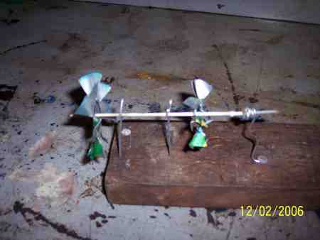
My first prototype was a paper water wheel and the water from a sink faucet (Picture 1). This seemed encouraging! Next I measured the water flow at 300 ml/minute. Twenty minute cook time would consume 6 liters of water, 300 ml x 20 = 6000 ml or 6 liters. This seemed hopeful. BUT, THIS IS JUST WILD SPECULATION CONCERNING THE VOLUME OF WATER NEEDED!
Picture 2 is of the fan. It was made from an aluminum pop can. A tin can would work also if not better.
Picture 3 shows the water wheel which was also made from the same pop can. Of course a tin can would be a better choice but aluminum is easier to prototype.
Picture 4 shows the coaxial assembly.
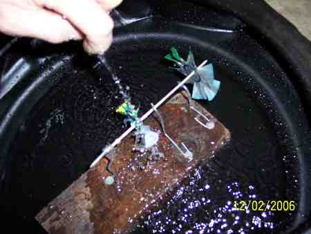
You will find the HydroFan in action in picture 5.
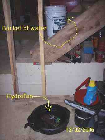
In picture 6 you can see the bucket of water and the HydroFan.
At this point in time I do not know if this is a practical replacement for the battery powered fan. If not, maybe it will help someone create a workable solution. However, if the HydroFan proves workable it would be best manufactured at the cottage industry level.
The book "Behemoth: The Story of Power" (www.knowledgepublications.com) was the source of my inspiration for the HydroFan.
Jeff Davis
New Arrivals - Check out the latest sneakers at Capital.


Comments
Jeff Davis replied on Permalink
Amount of Water
Kevin wrote:
1 Watt = .101 kilogram-meter per second
Assuming 100% efficiency of your turbine, then for each watt of fan power,
you will require .101 kg of water to fall through 1 meter.
If the waterwheel efficiency was 50%, then you would need .202 kg of water
flow per second for each watt of shaft power output to the fan. Each minute
would require about 12 kG water flow; each hour will require lifting about
720 kG of water a distance of 1 meter
If you require 3 watts of power to drive your fan, you would need to lift
about 2160 kG water per hour.
The system would work, but it would be tedious.
Best wishes,
Kevin
Jeff Davis replied on Permalink
Pumping Water
Peter wrote:
Both Kevin and I have been there and done this same energy discussion on
one of the lists a few years back. And the resulting discussion on just how
energy dependent we all are -- when you really look at the "measures" of
energy -- as you have just been presented with in this case.
So -- how to make an very economic source of energy with the parts and
pieces at hand??
Maybe by "value" adding??
How about an Atmospheric engine?? Which is as good a potable water
distiller as you can get -- plus kicks out some energy as a bonus??
A very low pressure (Typical 5 PSI) portable waster generator attachment --
boils water -- then condenses it. Only you condense it using a "Newcomen
Atmospheric Engine" --
NEWCOMEN LINK
Now use your creative instincts --
Water jacket ringing around top of stove -- no big deal there --
Steam so evolved flows under 5 psi pressure to Newcomen engine.
As your dealing with low temps ( 5 PSI saturated = 227 F -- and always
(unless you try this at the bottom of a very deep mine shaft) one can
probably adapt a common bicycle air pump as the working cylinder -- and no
need for a crank either -- just have the reciprocating motion operate a
"bellows" -- ya don't need high tech to blow air folks!!
You can design a very simple accumulator to smooth out the bellow pulses --
right??
Say a small bucket up side down in a bigger one filled with water ---
Or -- attach a second bike pump to it -- and that should get you at least
10 PSI pressure to pump up an old patched up car tube -- and you then can
bleed out through a small orifice a small high velocity stream of air.
Most stovers would be happier to have a little extra pressure small blow in
exactly the right spot -- rather than a low pressure breeze over everything
-- right folks??
The thing is the cost is covered by the dual purpose of this device -- it
produces distilled water -- pure water -- very potable water. The
relatively small amounts so produced is a life saver for babies -- as example.
See appended #1 for the technical description of theory of operation --
For this application one could run even lower pressures -- and no need for
that auxiliary pump -- one could then indeed hand lift "potable" water for
the water squirting condensing cycle.
Moving along either further ahead in "time" -- take a look at the
grandfather of all steam engines.
Ok -- have some real entertainment for a change -- and read all about this
fascinating subject at:
JAMES WATT LINK
Full of information such as this line:
"James Watt first made a cylinder of nonconducting material -- wood soaked
in oil and then baked and increased the economy of steam"
There you go Jeff -- a wooden steam engine -- what more could one want -- eh??
Stovers -- wooden steam engines to blow your fires with -- eh???
Anyway -- the history of James Watt at that Url above will certainly be an
extremely enjoyable read for many on this list -- and especially in these
depressing times -- so enjoy -- eh??
Never forget the advantage we have -- modern materials --- when you read it!!
There should be many the brain wave attack there to ---
Peter/Belize
>Kevin wrote:
>> 1 Watt = .101 kilogram-meter per second
>>
>> Assuming 100% efficiency of your turbine, then for each watt of fan power,
>> you will require .101 kg of water to fall through 1 meter.
>>
>> If the waterwheel efficiency was 50%, then you would need .202 kg of water
>> flow per second for each watt of shaft power output to the fan. Each
>> minute
>> would require about 12 kG water flow; each hour will require lifting about
>> 720 kG of water a distance of 1 meter
>>
>> If you require 3 watts of power to drive your fan, you would need to lift
>> about 2160 kG water per hour.
>>
>> The system would work, but it would be tedious.
>>
>> Best wishes,
>>
>
>
**********appended 1***********************
This magnificent engine was patented in 1705 by Thomas Newcomen, and is
generally regarded as the first 'modern' steam engine. Unlike later steam
engines, the Newcomen works on the atmospheric principle.
The Newcomen was first used to pump water from mines in England. The pump
rod at left is coupled to the driving piston by a large rocking beam.
Water is boiled continuously to produce steam. During the piston's upward
stroke this low pressure steam (about 5 p.s.i.) is admitted to the
cylinder. The pressure is insufficient to lift the piston on its own --
the weight of the pump rod does most of the work.
At the top of the stroke the steam valve is closed and a water jet is
briefly turned on, cooling the steam in the cylinder.
The cool steam contracts, sucking the piston downward. ...Or stated
another way: the higher atmospheric pressure drives the piston downward,
hence the name atmospheric engine. At the end of the stroke, the cooling
water is drained from the cylinder by an extra passage not illustrated
here.
During the upward stroke, an auxiliary pump fills the cooling water reservoir.
Newcomen engines were successful in part because they were very safe to
operate. Since the steam was under such low pressure, there was no risk of
a dangerous boiler explosion.
As near as I can tell, the earliest Newcomen engines featured manually
operated valves, as illustrated here. An operator apparently stood on a
platform near the cylinder base and threw the valve levers on each stroke.
(From the illustrations I have available, this engine seems to have stood
at least 20 feet tall). Later Newcomen engines featured automatic valves
which were coupled to a pushrod attached to the main beam.
Jeff Davis replied on Permalink
More on Pumping Water
Peter wrote:
Yes -- in the past Kevin and I were the Chimney promoting people as well --
I use that system on my process furnaces here -- one for drying the coconut
gratings -- the other for boiling down cane juice.
I developed (and this is years ago now) a very efficient and economic way
to build a chimney stack -- even in 3rd world.
I use regular thin gauge -- cheap sheet metal grooved roofing -- 16 ft
length works just fine -- roll it and pop rivet it!
But -- back to this present mission --
Jeff -- your HydroFan has great possibilities of being the correct answer
-- the pumping of the water can be easily accomplished in numerous ways
using steam.
In fact -- this was how the first steam engines came about.
Take a look at this Url:
CLICK HERE
Specifically:
Fig. 5.De Caus's Apparatus, A. D. 1605.
In 1615, Salomon de Caus, who had been an engineer and architect under
Louis XIII. of France, and later in the employ of the English Prince of
Wales, published a work at Frankfort, entitled " Les Raisons des Forces
Mouvantes, avec diverses machines tant utile que plaisante," in which he
illustrated his proposition, " Water will, by the aid of fire, mount higher
than its source," by describing a machine designed to raise water by the
expanding power of steam.
In the sketch here given (Fig. 5), and which is copied from the original in
" Les Raisons des Forces Mouvantes," etc., A is the copper ball containing
water; in, the cock at the extremity of the pipe, taking water from the
bottom, C', of the vessel; 1), the cock through which the vessel is filled.
The sketch was probably made by De Caus's own hand.
The machine of De Caus, like that of Porta, thus consisted of a metal
vessel partly filled with water, and in which a pipe was fitted, leading
nearly to the bottom, and open at the top. Fire being applied, the steam
formed by its elastic force drove the water out through the vertical pipe,
raising it to a height limited only by either the desire of the builder or
the strength of the vessel.
***********************************
Looks like water pumping problem solved for your hydroFan application in
the most simplest of manners -- and Look MA -- no moving parts!!
(As long as you have some waste heat of -- say -- 300 F or more)
Well -- say a couple of hand operated valves. First of all -- using this
system one can greatly increase the head of water (height of your
reservoir) -- easy to go 15 feet -- as example (About 7 psi steam pressure
would then be required)
So the amount of water flow would be much less.
Second -- the spent water is collected in a container at the bottom --
after it has done "work" in your HydroFan -- now -- here comes the cute part.
You run a pipe to the pumping chamber from the spend water return. That
pipe exits from the bottom of that water reservoir. and enters the top side
or bottom of the steam expansion chamber.
Once you steam expansion pump has depleted it water charge -- you close the
top valve and open the valve to the drain reservoir --
As long as the drain reservoir is a foot or so higher than the steam
expansion chamber -- water will flow into the expansion chamber --
condensing the steam there -- and thus drawing in the water from that
reservoir till full.
You then open the valve to pump water to the high reservoir -- and close
the valve going to the low one.
Cycle repeats -- water "pumps" --
Make sure your hydro pump is made of materials that can take -- say -- 180
F water.
Run the system hot -- and again -- a side benefit is even much more
purified water produced every day!!
When you stop the system you do so with the high tank charged -- so you
have that "energy" stored (classical potential energy) to start your fire
for the next time.
You further replenish by condensing as described the steam expansion pump
chamber with a fresh batch of water.
Next time you start up -- when the top tank runs down to fill the bottom
reservoir -- drain and bottle that -- it is "purified" cold water -- by
then the expansion chamber should have "pressure" -- and ready to pump up
the upper tank full again.
Once could also consider this a stationary Minto Wheel??
>From India:
CLICK HERE
or:
CLICK HERE
And never forget Jeff -- a "Dunk-Bird" could run a bellows!!
The mechanically inclined might well browse that entire WWW site.
CLICK HERE
Great reading!!
If we are going to dream -- at least let's do it in color??
The Dunk-Bird Stove!!
(Sounds like a winner to me!!)
Peter / Belize
At 01:04 PM 12/5/2006 -0500, you wrote:
>Dear Peter,
>
>On Monday 04 December 2006 11:15 pm, Peter Singfield wrote:
>> There you go Jeff -- a wooden steam engine -- what more could one want --
>> eh??
>
>I've thought about it before!!! I agree.
>
>That's why I like the Bisschop engine, power and heat. Your wooden steam
>engine would be simpler.
>
>When I get the time I will add Kevin's and your information to the article
>(HydroFan).
>
>It takes sometime to really understand how much power a stove uses/makes to
>move air. Keven's chimney makes a stove better at moving air. Amazing how
>much work a chimney can do. Maybe it was a bigger invention than the wheel.
>
>Volumetric efficiency, anybody?
>
>
>Jeff
Jeff Davis replied on Permalink
Woodgas Camp Stove
Tom wrote:
Dear All:
It's amazing to me how resistant many stovers are to using electricity
(1 to 10 W) to power the WoodGas stove. Weights, inflated tires,
thermoelectrics, windup motors, lots of ingenuity here.
The progress of the world has had a major dependence on electricity for
a century with all functions possible using it. How about a handcrank
vacuum cleaner? Dish washer? Clothes washer?
I understand that battery power is much more expensive for the people
that most need this stove, and throw away AA batteries, while now $0.25
in the US are unavailable in many parts of the developing world.
However, my local Home Depot, Wallmart, Lowes, ... all sell garden
lights for about $6 retail which include
* A solar charger
* Two rechargable AA batteries
* A light activated switch
* An LED light
I have examined my LED light and installed a power takeoff for my
woodgas stove. Whoever can get back to the source of these lights
should be able to market them for < $10, a small price for clean,
efficient cooking. But of course we are all inventors and need to work
our way through the other options.
Comments?
Yours truly,
TOM REED BEF STOVEWORKS WOODGASLLC
Jeff Davis replied on Permalink
Measure Air Volume
Tom wrote:
Dear All:
While it is nice to turn a know to adjust the fan or blower speed, the
simplest and most direct way is a piece of paper (etc.) over the air
inlet.
While we're at it, you can measure the output of the blower/fan
measuring the inflation time of a very light weight newspaper bag of
know volume. (I learned that from Fred Hottenroth, originator of the
Sierra Stove, about 1990.)
TOM REED The Simplifier
Jeff Davis replied on Permalink
Plastic Bag
Kevin wrote:
Dear Tom
Even better than a paper bag is a garbage bag, and better still is the very
thin polyethylene cover that Dry Cleaners use to cover their finished work.
The volume of these bags can be measured easily by filling the bag to the
shape it takes on when filled with air, using the light "foamed plastic
popcorn" that is used for packing goods for shipment. Then dump the foamed
plastic popcorn into a rectangular box and measure it, to get an accurate
indication of volume.
Best wishes,
Kevin