Crispin Pemberton-Pigott and Roger Samson, February 2010
Please click Read More for a set of photos showing the construction of a prototype 125 mm diameter Grasifier Stove burning Switchgrass Pellets provided by Roger Samson (REAP-Canada).
 01 Mark sheet 4 in and holes half in apart
 02 Use a washer and tapered punch to enlarge the holes
 03 Drill or punch 8mm holes
 04 Viewed from outside
 05 View from inside showing the nozzles formed by punching
 06 Cut a round plate for the bottom
 07 Press the plate down to the bottom
 08 The plate in place
 09 Set the steel pipe to the correct height
 10 Hammer the lip of the cylinder flat
 11 Drill 8 small holes then enlarge to 8mm
  12 View inside the combustion chamber
 13 Set the pipe height and hammer a flat lip of 5mm
 14 Cut a suitable triangle
 15 Fit the triangle into the air preheater
 16 Insert the combustion chamber into the preheater
 17 Press the combustion chamber down
 18 Lift the preheater to touch the top lip
 19 Make two holes for the handle
 20 Fit the handle
 21 Mass of the stove
 22 Press TARE
 23 Add 1000 g of fuel
 24 Pot rest in position - press TARE again
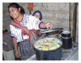
 25 Air holes opened to give high power, see steam jet
26 Lower air holes blocked, low power is 30 per cent less
The height of the combustion chamber is not significant. The line of secondary air holes are placed 4 inches (102 mm ) below the top lip. The holes are 5/16" in diameter (8 mm) and are formed by knocking a tapered punch into a small starting hole. A washer is used to do this. It creates an 'air spout' that blows air into the centre of the chamber.
This combustion chamber holds 1 kg of pellets - the top of the fuel must not be higher than the line of secondary air holes. The power is about 2.5 kW.
The char remaining after 1.25 hours was 275 g.
The eight 6 mm holes at the bottom can be used (in a primitive manner) to control the power level: leaving 2 or holes open is sufficient in the beginning. However as the volatiles are burned there is an increasing demand for primary air. If the holes are opened one by one, the char can be partly burned. If this is not done, a lot of smoke is created at the time when the flame is no longer sustainable. If you have been making TLUD stoves, please try this as the designs popularised so far seem to demand that the cook notice the smoking and quench the char in a covered can. Using the idea of increasing the primary air supply to keep the fire going, the char has lower volatiles than the type produced by the
fire>smoke>quench-in-a-can method.
The pot being in place creates a sheltered environment that allows the flame to burn much longer and can result in a (visually) clean extinction. If a disk with a central hole is placed at the top of the combustion chamber, it performs the function of keeping out cold down-drafts into the chamber on one side with flames being chased out of the chamber on the other. This part is unnecessary with this air supply layout (a Vesto-based design). Put on a pot to control the ingress of cold air at the top. If used as a heater, a perforated place will also do. The pot is part of the stove.
If the primary air is opened in time (before the volatiles are used) the flame continues for longer, then goes out. There will still be a CO spike at the end but it seems to eliminate the 'smoking phase' at the end.
Confirmation still needed. As the char yield was still 27.5% of the initial pellet mass, it cannot be considered Unproductive in terms of char.
It is estimated that the ash content of the remaining char is:
1000/275 * 4% = 14.5%
This gives a final heat content for the char of 15.5 MJ/kg, or 4.27 MJ remaining from this burn.
The total yield of heat was approximately 13 MJ over a period of 80 minutes (4800 seconds) for a calculated average power of 2.7 W.
The thermal efficiency on both High and Low power was 30% (Low is 70% of
High) using a large pot with >3 litres of ice water in it.
Given the high power in such a relatively small stove, the flames are quite short. This is because there is an adequate but not excessive secondary air injected below the pot so that the flame barely touches the underside. This limits the formation of soot and helps burn Carbon-Monoxide (the blue flame).
By type, the stove layout has a Tsotso style secondary air pre-heater with Vesto-like secondary air entrance and direction of that air, all with a choked primary air supply. In order to turn it into a Vesto, add a third shell around the outside no higher than the secondary air hole entrance (not the full height of the stove). There is no control over the secondary air supply which rises between the outer cone and the combustion chamber within.
The stove weighs about 500 grams. The materials would cost about $1.50 if executed in a low chrome stainless steel such as 3CR12 or SS 430. This one is made from scrap 26 and 30 gauge sheet metal.
The pot stand is 12 mm high and could be reduced to 10 mm. The Grasifier can considered to be a combustor, not a stove. It can be placed into any of dozens of stove bodies such as a Lorena clay stove or any metal or brick constructions that can support the pot properly. The handle, used to remove the combustor for emptying and re-filling, should be shortened to fold next to the top lip if it is installed in a larger stove body. It can then be removed with a hook.
Crispin Pemberton-Pigott
crispin@newdawn.sz
23 Feb 2010
www.newdawnengineering.comFASHION NEWS