High Performance Combustion with a Simple Technology
Alex English, 553 Maple Rd. Odessa, Ontario, Canada K0H 2H0 , Nov.15 2000
Presented to the International Conference on Biomass-based Fuels and Cooking Systems 2000
Nov 20-24, 2000 Pune, India
Pictures from the conference.
Introduction.
The small scale use of biomass as an energy resource can be as harmful as it is necessary. The search for simple ways to burn plant materials usefully while minimising harmful emission has proven difficult. Solid biomass fuels have tended to perform poorly when compared to fossil fuels. (Smith et al. 1999 and Smith et al, 2000) Control over fuel and air mixing is paramount in any combustion process. Biomass pyrolysis and gasification are potential ways to change solid fuel characteristics and gain control over fuel/air mixing. This report gives a brief account of recent tests of a promising new approach to biomass energy conversion at a small scale.
Concept overview.
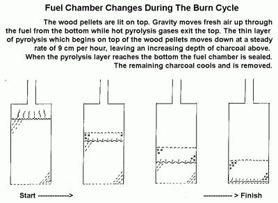
Pyrolysis is the destructive distillation of organic material. This air limited combustion, or flaming pyrolysis of dry plant materials, releases its volatile components as a mixture of combustible gases. A carbon rich char containing most of the ash is left behind.
In this case pyroysis takes place in a closed column moving down through the column after being ignited on top. This process controls the rate of release of the volatile products of pyrolysis. (Reed and Larson,1996)The rate of gas production is partly controlled by the amount of air admitted to the column. ( see figure 2 under Operation.)
One way to assess this process is to develop a practical means of burning these gases and then analyse the gaseous products of combustion. The gases and smoky particles released from this top to bottom process form a rich fuel that must be continually mixed with the correct amount of air for good combustion to be maintained.
Good burner design can not hide poor gas production from the process of pyrolysis. However poor burner design or operation can hide evidence of a stable production of combustible pyrolysis gasses. The two components of this device are necessarily judged together.
Ideally, for this concept to have merit for people with limited access to modern resources, it must not rely on complex material or mechanical devices. For this reason these tests were conducted on two simple designs which required no electricity to operate, and no exotic materials to build. These two pyrolyser/burners were built only for testing this concept, and are not meant to be prototypes of practical stoves.
Test Method
The ratio of CO/ CO2 in stack emissions from the combustion of carbon containing fuels is a common reference for combustion quality. (Khan and Hasan, 1991) Individually CO and CO2 level variations reflect on the stability of the combustion process.
During these two tests stack gases were sampled from the chimney, cooled, dried, filtered and analysed by a continuous CO and CO2 analyser. The output from this analyser was continuously logged on a PC.
K type thermocouples were also logged as another gauge of process stability and characteristics. Both pyrolysers had stack exit thermocouples. The large pyrolyser had a thermocouple at the exit of the fuel chamber to measure pyrolysis gas temperature, and one, buried in the pellets 23 cm from the top of the fuel.
All outputs were in millivolts, and as graphed, have only relative value. The actual values of CO and CO2 were noted during testing. CO was also checked with a more sensitive hand held monitor.
Apparatus and Fuel
Two devices were used for these tests. A large pyrolyser with a fuel capacity of 0.17 m3 and a small pyrolyser with a capacity of 0.02 m3. (See figure 1. below) Both of these depend on bouancy or "chimney" affects to draw air into the process. Both have secondary air ports into the burner, which create a vortex to enhance mixing before and during combustion.
The fuel used for these tests was dry wood pellets with a bulk density of about 585 kg/m3. The large pyrolyser was filled with 100 kg of wood pellets, creating a fuel column depth of 106 cm. The small one was filled with 8 kg of pellets leaving a fuel depth of 20 cm.
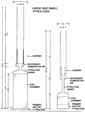
Fig 1. Large Pyrolyser/Burner on the left and the Small P/B on the right. (Individually to scale)
Operation.
The basic operation of each of these two models is as follows.
- Fuel chamber is filled with wood pellets.
- Pellets are lit on top.
- Pellets are allowed to burn for a few minutes until pyrolysis has moved down into the fuel and spread over the entire top surface of the fuel.
- Gas and air mixture is lit in the burner.
- Flame is sustained until fuel is completely turned to charcoal.
- Fuel chamber is sealed and allowed to cool.
- Charcoal is removed
.
The small pyrolyser is different from the large one. It comes apart between the fuel chamber and the burner, and the large pyrolyser does not. When the small pyrolyser is lit it is allowed to burn on top in the open until the burner is placed on top. The large pyrolyser is lit through a port above the fuel and exhausts into the burner from the moment it is lit. The port is then sealed. Both burners are lit with pilot flames until gas production is sufficient to support self-ignition in the burner. Primary air supply into the bottom of the fuel chamber is left fully open at the beginning. For the large pyrolyser primary air was not adjusted. The size of the holes in the grates is different for the two fuel chambers. The small pyrolyser required some operator control over primary air to moderate pyrolysis gas production. Secondary air was adjusted for both burners. During these tests the operator adjusted the air supply levels to achieve the best results based on the stack gases being monitored, and on the visual and auditory characteristics of the flame.
The test on the large pyrolyser was stopped before the region of pyrolysis had reached the bottom of the fuel column to allow for an inspection of that region. This was done by plugging the air inlets to the fuel chamber.
The test on the small pyrolyser was allowed to continue after the region of pyrolysis had reached the bottom of the fuel chamber, as assessed by the glowing hot colour of the primary air grate. At this point there is a transition from the top-down process of raw fuel pyrolysis to the gasification, and ultimate consumption to ash, of the remaining column of charoal at the grate. With some adjustment of air supply, the flame in the burner was maintained.
Results and Discussion.
1. Large pyrolyser
The results of this test are best reviewed in the context of the data collected.
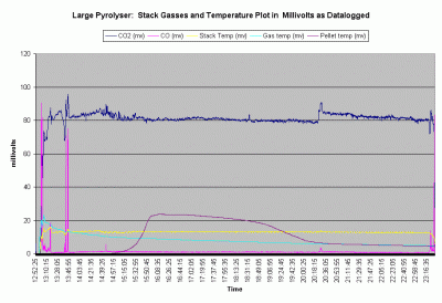
Graph 1. Shows all the data points as collected over the 10.5 hour duration of the burn.
This is the best way the author has to display the relative changes of the five outputs.
Results.
The data shows that after 45 minutes the combustion process settles down and remains
very stable for the remaining 9.5 hours of the burn. Actual levels for CO2 remained between 12% and 14% with only one operator adjustment to air supplies. CO levels remain stable around 100 ppm during the same period. CO/CO2 ratio for the majority of the burn was below .001
Discussion.
The supplementary heat used to start the burn on top of the pellets was withdrawn at 13:10. The supplementary ignition source in the pyrolysis gas burner was withdrawn after an additional ten minutes. The instability shown in the CO2, CO and stack temperature until 13:45 is primarily due to the operator continuing to adjust the secondary burner air to maintain a flame. The pyrolyser was left to operate "hands off" for almost 7 hours until 20:30 when the secondary air was reduced slightly. Primary air was not changed until 23:20. Shortly after this the burn was stopped intentionally before the fuel was completely pyrolysed. Inspection later revealed that the region of pyrolysis was a horizontal layer no more than 2 cm thick and that a depth of 13 cm of unpyrolysed fuel remained from a begining total depth of 106 cm. This means that the layer of pyrolysis moved down through the fuel column at a rate of about 9 cm/hour.
The stack temperature was very stable for the last eight hours of the ten and a half hour burn. Pyrolysis gas temperatures, which were initially affected by the flames on top of the fuel, showed a continuous decline over the course of the burn cycle. This was likely due to increasing distance between the pyrolysing layer in the fuel and the temperature probe. This increased both the exposed surface area of the fuel chamber and the transit time, which intern affected the total heat lost by the pyrolysis gases. The pellet temperature at the point of that thermocouple remained at ambient levels until the pyrolysing layer moved down to it, where upon the temperature climbed to a peak over the course of an hour. The peak pellet temperature was approximately 600C. A gradual drop occured as the pyrolysing layer moved down away from the probe. The probe was then monitoring the temperature of the newly produced charcoal pellets. It then droped quickly at about 19:10 when the top of the shrinking fuel column dropped below the thermocouple and exposed it to direct radiant cooling from the chamber walls. At this point it ceased to be monitoring the charred pellet temperature and begins to monitor relative pyrolysis gas temperatures.
2. Small Pyrolyser
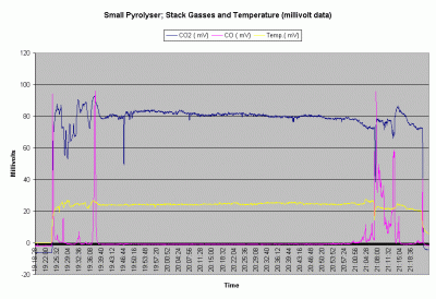
Fig. 5. This graph shows the relative changes over time of the three data outputs.
Results.
The data showed that after and initial start up period of adjustment lasting 15 minutes, the combustion process was very stable. During the central 1.3 hours of this burn, actual CO2 level remained between 12% and 14% and CO remained below 10 ppm. For the majority of the burn the CO/CO2 ratio remained below 0.0001. Instability at the beginning of the burn was likely due to the operators adjusting air supply to establish a stable flame. Instability at the end was due to necessary air adjustments to prolong the burn during the char gasification stage. The burn could have been terminated earlier for the maximum charcoal yeild.
Discussion.
The stack gasses are monitored from the moment the gas burner is placed on the burning pellets in the fuel chamber. This extinguishes the flame that then has to be lit in the gas burner. All this happens at about 19:24. The operator then adjusts primary and secondary air to maintain a good flame. No burner adjustments were made between 19:39 and flame out at 21:07. During this period stack CO2 concentrations varied little while CO varied even less. The dip in CO2 at 19:47 is due to a hose change on the gas sampling apparatus. CO was periodically checked with a handheld gas analyser and remained below 10 ppm.
After 21.07 the operator experimented with the transition to updraft gasification of the remaining char in the fuel chamber.
Discussion of both Pyrolysers.
While the large pyrolyser demonstrated the feasibility of long cycle duration using batch pyrolysis, the small model demonstrated some advantages for its burner design. While CO emissions were excellent for the large pyrolyser, they were extraordinarily low for the small one. The burner design of the small pyrolyser includes a long pipe for the pyrolysis gas to travel through. This acts a chimney for the fuel chamber and stabilises the primary air flow rate into the fuel chamber. Instability during start up with the large pyrolyser continued much longer and may be due to a lack of chimney effect between the pyrolysing fuel and the pyrolysis gas burner.
It should be noted that the operator of these pyrolysers had the benefit of exceptional information to help set up the air flow parameters for this test. This biases the results towards a favorable outcome. In normal operation either preset air supply ports or some other means of flame optimization would be required. During these tests it was observed that there was some correlation between the flame noise, flame height and measured levels of CO and CO2. These more subjective observation offer a possible alternative approach for the operator to practically assess the burners performance.
Both pyrolysers ultimately produce charcoal as a co-product. The yeild is generally between 20 and 25 % of the intitial mass of wood pellets. The bulk density of this pellet charcoal is approximately 282 kg/m3.
Conclusions
Poor combustion quality and control often limit the optimum conversion of solid biomass to useful energy at small scale. This exploratory look at the top-down approach to dry biomass pyrolysis, show that it can be an effective means of regulating fuel feed rates which, in turn, can facilitate obtaining a high quality of combustion. This approach also offers a clean and potentially energy efficient alternative means for producing charcoal.
This approach also demonstrates the feasibility of obtaining these results with a fairly simple technology.
These results were achieved using a high quality of processed biomass fuel. It is unlikely that comparable results will be attained with fuel of a large and irregular size and higher moisture content, however many other fuels remain as possible candidates for this process.
References:
Greenhouse Gases From Small-Scale Combustion Devices in Developing Countries:Charcoal Making Kilns in Thailand, December1999, Kirk R. Smith et al. United States Environmental Protection Agency,
EPA –600/R-99-109
Greenhouse Gases From Small-Scale Combustion Devices in Developing Countries: Phase IIa, Household Stoves in India, June 2000, Kirk R. Smith et al.
United States Environmental Protection Agency,
EPA-600/R-00-052
T. B. Reed and Ronal Larson, 1996, A WOOD-GAS STOVE FOR DEVELOPING COUNTRIES, The Biomass Energy Foundation, Golden, CO., USA
Khan, A.M. Hasan, R. 1991, Clean Combustion of Wood: Part II, Woodcombustion Studies Part 2,Woodburning Stoves Group, Eindhoven University of Technology, Eindhoven, The Netherlands.
--------------------------------------------------------------------------------
R.A. Sampson, 1999 and 2000, Personal communication and several studies about pellet fuels based on agricultural residues.
Resource Efficient Agricultural Production, Box 125, Glendale House, Ste. Anne de Bellevue, Quebec, Canada H9X 3V9 www.reap.ca
see the following studies
Opportunities for Improving Agricultural Sustainability as a Strategy to Enhance Bioenergy Development :
The Case in Sugarcane Production
STRATEGIES TO AVOID CROP RESIDUE BURNING IN THE PHILIPPINE CONTEXT
Mitigating Greenhouse Gas Emissions through Energy Supply and Demand Options for Cooking in Developing Areas
