Crispin Pemberton-Pigott, New Dawn Engineering, Swaziland, March 2006
Dear Stove Builders
Getting stove dimensions, particularly pot-stove body clearances, is no simple matter because of the many different considerations that must be resolved simultaneously.
You must Create an Account and Login to see the file.
I have forwarded the attached Excel spreadsheet to Tom Miles which he has also posted on the REPP site for downloading.
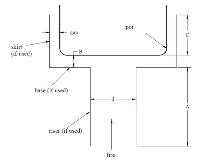
This sheet tries to address the problem of sizing the space and taper of the gap under a pot, and the gap between the skirt and the pot, taking into consideration the pot size, the combustion chamber size, and the variation in the volume of gas as it cools along the pot. Some experimentation will be necessary to go to a completely predictable result. There is space to accumulate data from a number of tests.
Some users might be surprised by the dimensions given as outputs. In general, the gaps should be smaller than have heretofore been estimated.
One issue to be addressed with building stoves is excess air: air that passes through the stove which is not required for combustion. The spreadsheet allows you to enter a percentage of the combustion chamber area that will be used as the input for the size of the gas path. The idea is that the formula for calculating the combustion chamber size (posted separately) gives a space that is required for the wood to be burned, but which is actually too large for the gas path through the rest of the stove.
Most stoves have an unnecessarily high excess air ratio. This calculation is accomplished by choosing a percentage of the area of the combustion chamber, for example, 70% of the total, and using this as the gas path cross-sectional area. The pot can be used to throttle the system until the excess air ratio is between 50% and 300%. Once a stove is built and tested, the percentage number used can be directly tied to the excess air ratio and future adjustments made.
In addition, there is provision for entering the temperatures of the gas at three points: the lip of the combustion chamber, the bottom outside corner of the pot, and at the exit point of the skirt. These temperatures are used to calculate the correct reduction in volume of gas in various places.
These should be entered for the high power condition. If they are not, there is a chance the stove will choke due to lack of air. If you have an oxygen meter, you can detect this condition and either increase the percentage figure used, or reduce the maximum amount of wood that can be burned at one time.
In the past a set of shreadsheet cell formulas was forwarded in an email for discussion. This spreadsheet incorporates these and a number of other functions including automatically sizing the combustion chamber to the pot size (actually, the diameter) and it gives the cone angle for the top of the combustion chamber under the pot and even the vertical taper of the skirt.
The basis of the cone calculation is that the velocity of the gas will be constant throughout the stove as it cools. It is not compensated for the change in the heat transfer efficiency as it varies with temperature, a complication which can be addressed at a future time. In any case it might result in a shape that cannot easily be made by hand.
There is a page for round combustion chambers and another for square ones, plus a third for skirts.
People may find the firebox sizing formulas mysterious, arcane or even bizarre. Don't worry! They are based on empirical data from Aprovecho's work on stove sizing as made available in their firebox sizing charts which are the result of years of testing. The formulas are a best fit and will no doubt be made more accurate as time goes by. In the meantime, this tool provides a very useful guide to optimising the shape and performance of single-pot stoves.
Best regards
Crispin
New Dawn International
crispin@newdawn.sz
 |
|
GAP AND SKIRT DIAGRAM FROM ANDREATTA: HEAT FLUX REPORT 2006
|
LINKS:
See Dale Andreatta, Heat Flux Report January 2006, ETHOS, January 2006 (pdf)
Nike
