The Poor one press
©Legacy Foundation Sept., 2003
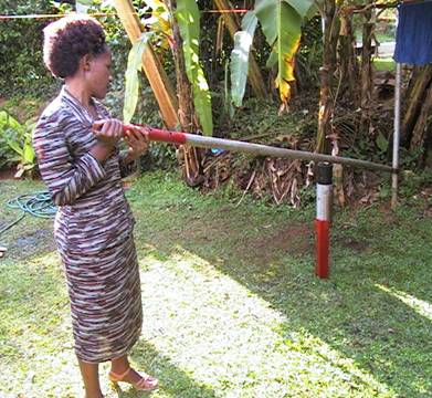
Is single 12 ft (3.5 meter) long lever and special eject stand. It uses the same mold set as with the mini and maxi
Bryants and like those production presses, the Poor one involved a simple batch fed operation. Unlike the production presses, the Poor One is far easier and cheaper to build. However, the Poor Man is limited to certain blends which are easy dewatered and readily release fibers to form a tight bond under relatively low pressures.
The parts
Handle:
This is simply, one 2" dia GS pipe of a12 ft (~3.5 mtrs) length which is pivoted at its far end by any means (stuck into a hole in a tree, tied with rubber tyre strapping onto a telephone pole , stuffed into a notch in a rock etc.) It is attached to same, about 12 inches (30 cm) off the ground. The first four feet of this pipe may need reinforcing with 1"x 1/4" steel bar stock or additional 1" gs pipe welded or rubber wrapped along the top the beam, if heavy loads are to be encountered.
Eject stand:
The stand is prepared by cutting two 1" deep slots, laterally opposite each other into the sides of a three ft long piece of angle iron with 1&1/2 " wide sides. The slots are located about 5 inches down from what will become the upper (exposed) end of the stake. The lower sides of these slots are then bent slightly inward to create a "lip" or a "step" which is 4 to 5 mm wide at its widest point.
Make sure that the lip cannot be seen when you look down through a 4 inch heavy duty PVC pipe ( such as the same pvc pipe used for the cylinder mold) resting on these lips. Bend the lips back to ensure this visual clearance, if necessary.
Finally, a partial ring of any scrap 3/8" (10mm) dia. rod is welded onto the upper 5 inches of the stake such that it forms a lateral circle connecting the two sides of the angle iron with a minimum dia. of 4.5 inches. This ring will be used to hold the cylinder in place as the piston is pressed down through it. Hence the term "retaining ring" is used to describe it. check to make sure as well that the retaining ring allows the same pvc pipe cylinder can be easily slid through it and down onto the mentioned lips. However the ring should not be so loose as to let the cylinder slipping off these lips. You may need a scrap metal stop welded onto the angle iron at 16 inches in from the lower (ie non-slotted) end, to prevent the stand from sinking into softer ground.
Using a block of wood as a buffer to prevent damage, pound the stake into the ground about 4 ft out from the pivot end of the main handle pipe and offset it 2 to 4" from the track of the main handle/ lever. Leave 20 inches exposed. When finished it will look
like an oversized tent stake, then meticulously file everything smooth.
Side view of stand below. Note: the position of the ring in this early prototype is not to the dimensions suggested above.
Thats it .
Base block and Mold set
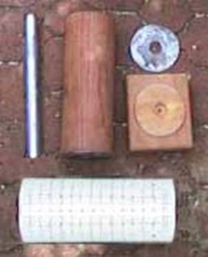
The base block and mold consist of from left to right
The guide pipe the piston (black color in initial photo above) a divider washer the base block and at bottom the PVC cylinder,(grey color in initial photo above)
The guide pipe is a 1’ GS water pip 11” inlength.
The piston is a 3 7/8ths inch dia X 11” long hollow wood “log”. The trik is in making a 1 1/8” dia hole thgough the center . If you do nto have a lathe or a long boring bit , use two 2 x 4’s each half is givena long trough large enough to easily contain the guide pipe. When you nail them together and plane down the square sides to a cylinder shape, you get the hollow cylinder. Be usre to allow lots of sloppy room for the pipe as it is a headache to clean it out after you have joined the two halves together.
Operation
Similar to the processes used for the compound lever press. With the mold set charged, the cylinder is compressed, starting as far from the pivot as possible, and working your way back to it. You then remove the base of the mold and slip the remaining mold cylinder (with piston, briquettes and center pipe all intact), through the ring on the "eject" stand, such that it comes to rest on the two lips or steps. Lifting the handle again and pressing down on the piston forces the briquetes out the bottom end of the cylinder and voila ! depending on how many dividers you used in the mold, one, two, or three briquettes are born.
Theory and applications.
Mechanics are simple pressures are direct linear through this range of movement of the handle. The leverage is of course limited to pipe length and to how close you can place the mold set to the pivot. In the little practice a local team here has had with it, this point appears to be about 1 ft out from the pivot so that at its maximum therefore, the 12 ft long handle gives 12::1 . This is about half of the compound lever press mini Bryant and about 1/3 that of the maxi Bryant but for many of the simpler blends using a combination of non compressible and very easily compressible materials, it is quite adequate to generate the necessary random distribution of inter locking fibers necessary to make a solid briquette.
Air Force 1


