
ROCKET STOVES - IN SEARCH OF HIGHER TEMPERATURES
(Variations in the size and location of air openings in a modified “rocket stove” and their effect on exhaust temperatures)
by Damon Ogle July 20 2002
INTRODUCTION
The “rocket elbow”, developed by Larry Winiarski and Aprovecho Research Center has proved to be a very effective combustion chamber for use in a variety of wood stoves built in underdeveloped countries. Testing at Aprovecho Research Center and experience in the field have demonstrated that a 5”diameter (or 4 ½”square) “rocket elbow” is a desirable size for actual cooking and is incorporated in several stove projects in Central America.
Standard geometry for a “rocket elbow”, see Capturing Heat Two, pg. 23, recommends placing a shelf in the mouth of the combustion chamber 1/3 of the way up from the bottom of the feed tube. A single layer of sticks (with air spaces between) is placed on top of the shelf and some free air enters above the sticks. Air entering under the shelf is partially preheated and passes up through the burning sticks. As the sticks burn off, the “charcoal “ ends fall into the bottom of the combustion chamber and a portion of the “under shelf” air passes through this “charcoal” layer
The cross sectional area of a 5” feed tube is about 19 1/2 square inches with about 71% above the shelf and 29% under. The percentages of cross sectional area for four components: (1) sticks, (2), air “above sticks”, (3) air between sticks and charcoal layer, and (4) air through the charcoal layer, are unknown.
The purpose of this experiment was to construct a stove in which the cross sectional area of each of the 4 components is measurable and adjustable. The total cross sectional area was held constant at 19 ½ square inches but different percentages of air were directed to different areas of the stove. The output temperature of the stove was measured for each of 9 air input configurations to see if air input had an effect on exit temperatures..
RESULTS
| Cross Sectional Area (%) | Exit Temperature (deg F) | |||||
| sticks | above sticks | mid-level | under charcoal | Max T | Min T | Est Mode |
| 12 | 59 | 23 | 6 | 1429 | 921 | 1175 |
| 12 | 50 | 23 | 15 | 1441 | 1050 | 1208 |
| 12 | 40 | 23 | 25 | 1380 | 1040 | 1200 |
| 12 | 30 | 23 | 35 | 1510 | 1025 | 1283 |
| 12 | 20 | 23 | 45 | 1595 | 1148 | 1383 |
| 12 | 10 | 23 | 55 | 1839 | 1311 | 1625 |
| 12 | 10 | 15 | 63 | 1810 | 1379 | 1641 |
| 12 | 10 | 7 .5 | 70.5 | 1846 | 1439 | 1658 |
| 12 | 10 | 0 | 78 | 1880 | 1481 | 1733 |
These results are the average of three “runs” each at 9 different settings. “Estimated mode” represents the averages of my best guess of the temperature around which exit gases hovered during each period of observation. Minimum and Maximum Temperatures are actual measurements for the period. The highest temperature observed during the tests was 1921 F.
EXPERIMENTAL EQUIPMENT AND PROCEDURE
STOVE
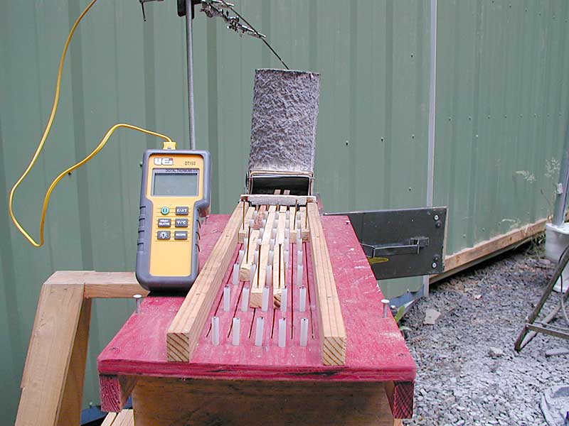
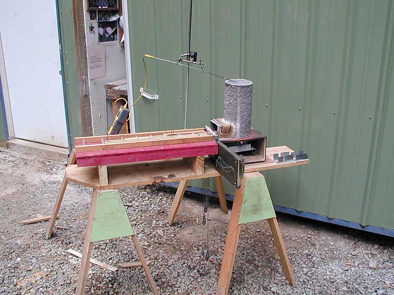
A rocket stove was constructed of sheet metal using a 5”diameter by 12”tall ceramic fiber “riser sleeve” for an insulated chimney. The feed magazine was 3” high by 4 ½” wide with an adjustable flap at the top to control the free air entering above the level of the feed shelf. Two inches below the feed shelf level a stainless steel screen (1/8’ mesh) was placed as a grate for the “charcoal” which fell from the burning sticks above. Air flow upward through this screen was controlled by 2 opposing horizontal sliding plates located 1” below the level of the screen. Air entering the stove above the level of the charcoal but below the level of the feed shelf was controlled by rows of 10 holes (3/4”in diameter) drilled in the wall of the chimney and in a surrounding ring of sheet metal. If the outer ring was rotated so that all holes lined up, a maximum of 23% of area was available for air entry at this mid-level. The entire bottom of the stove (below the feed shelf) was encased in an army surplus “ammo can” to provide access for adjustments to these two lower dampers.
FUEL
Douglas Fir was sawn in ½”wide by ¾”high by 12”long pieces and dried in an oven at 200F for a minimum of 8 hours.
FEED MAGAZINE
An automatic feed mechanism was constructed to feed 6 sticks at a time into the feed opening of the stove. This device used 5 oz fishing weights to maintain constant pressure on the 6 evenly spaced rows of wood being fed into the stove. Contrary to all expectations, this apparatus was remarkably trouble free. This arrangement allowed the cross sectional area of the wood entering the stove to be held constant at 2.25 square inches (12% of the total).
 |
 |
| A self feeding devices can be simple and functional | This photo shows the air inlets under the Rocket chimney. Experiment showed that air coming up through coals results in highest exit temperatures below the pot. |
THERMOMETER
A VEI brand digital thermometer with a 1/8” diameter stainless steel probe was used to measure and record exit temperatures from the stove. The thermocouple was fixed 1” below the top of the rocket chimney and directly in the center of the tube. This thermometer has a “record” feature which included a timer and records the highest and lowest temperatures for a given time period.
ENVIRONMENT
Tests were conducted in a sheltered outdoor area at Neskowin, on the Oregon coast. Tests were conducted over the course of several days in early July. Temperatures and weather conditions were fairly constant and wind was minimal.
PROCEDURE
- Outside air temperature and weather conditions were recorded.
- The feed magazine was loaded and the fire was started using ½ a sheet of newspaper and a small amount of finer wood. New sticks were added to the magazine as fuel was consumed.
- The stove was allowed to run for 20+ minutes to allow a stable state to be reached.
- After each new setting of adjustments was made, the stove was allowed to run for 2 minutes before recording was begun.
- Temperatures were recorded for a period of 8 minutes for each setting. During this time the thermometer was observed and a visual estimate was made of the mode temperature. At the end of this period, the estimated mode T, actual maximum T and actual minimum T were recorded.
- Adjustments were made to the damper settings and the procedure was repeated until all 9 variations had been recorded.
- At the end of each run, the coals were allowed to burn off from the screen. Very little charcoal remained and the screen stayed fairly open and clean.
DISCUSSION
The results of this experiment seem to indicate that location and size of air inlets does have a noticeable effect on the exit temperatures of the stove. In general, the less air entering above the feed shelf and the more air entering through the “charcoal” layer, the higher the exit gases temperature. The most noticeable jump in exit temperature took place when the air space above the feed shelf was minimized at 1/8” above the level of the sticks. This represented 10% of the total cross sectional area (6% between the sticks and 4% in the 1/8” gap above the sticks, which was needed to allow for “kick-up” of the sticks as they were fed into the combustion chamber). This observation seems to confirm the possibility that excess air entering the chimney above the feed level cools the exit gases more than it produces heat by encouraging combustion of pyrolysis products
No instruments were available to measure actual airflow, but it is reasonable to suppose that cross sectional area and air flow are closely related. Even with a full load of coals on the bottom screen, there appeared to be unimpeded flow of air at all times.
The stainless steel screen seemed to be structurally sound after some 10 hours at very high temperatures. Perhaps this is because cool air is continuously entering on the bottom of the screen. Only time will tell how long it will actually hold up, but I am encouraged by its performance so far.
The thinner sheet metal in other parts of the stove was oxidized and almost worn through in some places. It will have to be replaced before further experiments can be performed.
As one would expect, there were more and higher flames visible at the top of the chimney when higher exit temperatures were obtained. More smoke was also observed at these higher temperatures. This suggests that higher temperatures alone are not sufficient to clean up combustion. Previous work at Aprovecho by Nordica Hudelson, see Global Modeling and Testing of Rocket Stove Operating Variations, pg. 12, has suggested that limiting draft provides more efficient combustion.
CONCLUSIONS AND RECOMMENDATIONS
The exit gas temperatures in a “rocket” stove are strongly dependent on the size and location of air inlets.
Air entering the rocket stove above the level of the sticks in the feed opening tends to cool the exit gases of the stove.
Air entering at the “mid-level” (below the sticks but above the coals) is less effective in increasing stove temperatures than air being forced up through the coals.
Exit temperatures can be increased by minimizing the air which is allowed to enter the stove through the area above the feed shelf and maximizing the air which is forced to pass upward through the coals underneath the feed shelf.
REFERENCES
Hudelson, Nordica A., Bryden, K.M. and Still, Dean;Global Modeling and Testing of Rocket Stove Operating Variations. Department of Mechanical Engineering, Iowa State University, Ames, IA 50011-2161
Still, Dean, Hatfield, Mike, and Scott, Peter; Capturing Heat Two. Aprovecho Research Center, Cottage Grove, OR 97424