MINISTRY OF ENERGY AND MINERAL DEVELOPMENT
ENERGY ADVISORY PROJECT
DEVELOPMENT AND TESTING
OF BIOMASS ENERGY EFFICIENT TECHNOLOGIES
Terms
of Reference
1. BACKGROUND
In
For this reason, one of the
specific objectives of the Energy Policy for
This exercise is to be
carried out in collaboration with the Uganda Industrial research Institute which
among other things will provide the space where the experiments will be
conducted.
2. SCOPE OF WORK FOR THE BIOMASS TECHNOLOGY EXPERT
a) To design, produce and test a single pot metal rocket
stove
b) To design, produce and test a two pots clay rocket
stove (rocket Lorena)
c) To design, build and test an efficient bread oven
using woodfuel
d) To design, build and test an efficient institutional
stove using woodfuel
e) To draft and draw stove/oven technical diagrams
f)
To produce a
general brief mission report and one detailed technical report for each
stove/oven (rocket stove, Lorena, bread oven, institutional stove) developed
including plans, technical production details…
3.
TIMING
The length of contract will
be for 3 weeks, from Aug 15th to Sept 7th.
Week 1:
To
fire insulated bricks with Pumice/clay and vermiculite/clay and sawdust/clay,
develop a number of prototypes with fired and unfired mixtures for the market
rocket stove, and meet with local stove-building partners.
At the end of the first
week, the stoves will be demonstrated to a group of women with the help of NGO
partners. The stoves will then be placed in people's homes in the peri-urban
areas around
Week 2:
To
improve the bread oven, the institutional stove and the single pot commercial
Rocket.
·
Improve the
market stove (per the women’s recommendations from the demonstration) and the
insulative mix.
·
Visit an
existing wood fired bread oven site to see their cooking methodology
·
Build and test
an improved bread oven (see RETAP-Kenya model)
·
Visit
institutional stoves in schools built by Mr George Sizoomu and Mr Kawere
Muhammad and improve them.
·
Based on the new
Aprovecho prototype of an improved (insulative) Lorena stove, improve the
existing one and build an improved one at the research center and then one in
the field.
·
Meet with the
women who are beta testing the stove to garner their further impressions and
find out if the stove is suitable to their cooking task. If not the stove can
be modified and then returned to them ASAP.
Week 3:
Monitor field tests and develop a monitoring plan for
the 4 stoves/oven
·
Controlled
cooking tests against the open fire in the center
·
Monitoring in
the field
·
Prepare reports
Abbreviated Draft
Report
Introduction
of Rocket Stove Cooking
Devices in
Prepared
by Peter Scott/Aprovecho
GTZ-EAP Consultant
From August 12th to Sept 12th, Peter Scott,
working in concert with GTZ-EAP staff, independent stove producers, and members
of the local community developed a number of cooking devices that were unique
to Central Africa
Table of contents
2
Training
3
Cooperation with
George Sizoomu
4
Household
assessment of domestic single pot stove
6
The Fixed
Institutional Stove
7
The Portable
Institutional Stove
8
Vernacular
Insulated Ceramic
Appendix A Calculating the saucepan/stove gap
Appendix B 25 quotes from Sam Baldwin
Appendix C Rocket Stove Design Guide
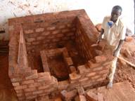
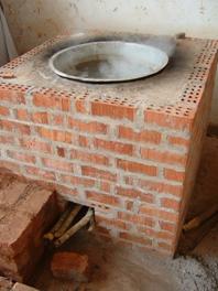
 1.1
1.1
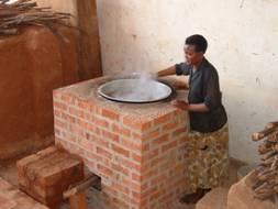
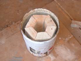
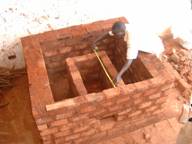
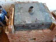
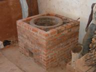
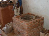
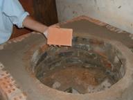
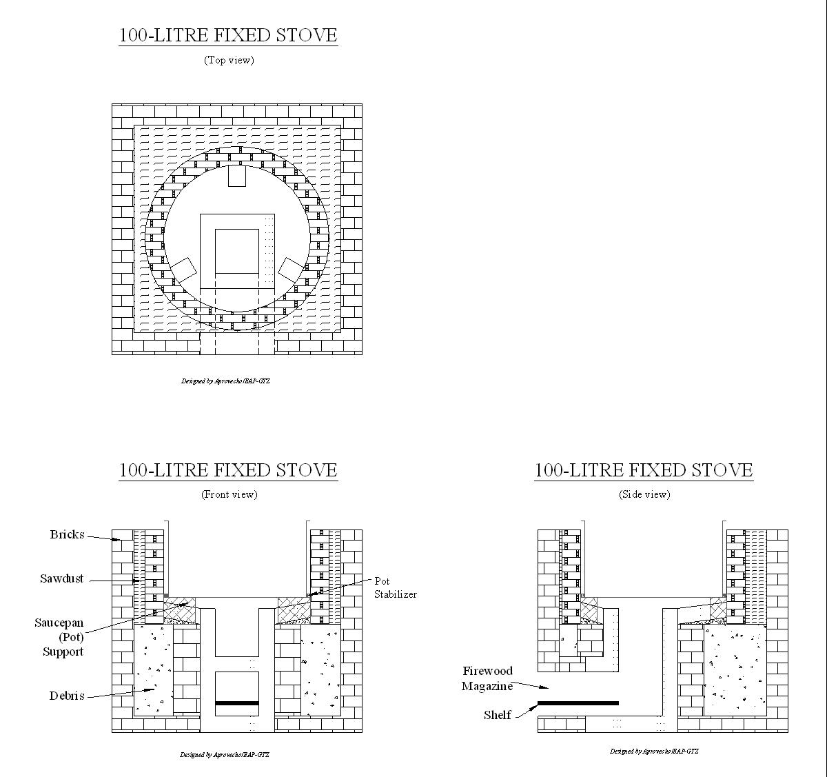
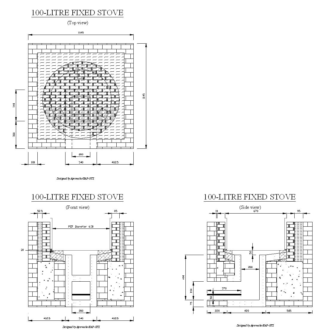
One 100 L fixed
institutional stove made with insulated ceramic (VIC) and Kajansi firebrick
was constructed at UIRI. This stove can be built with or with out chimney.
Chimneyless model is shown here. Note the absence of smoke above the pot or
large amounts of wood in the combustion chamber
1.2
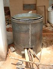
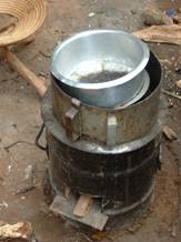
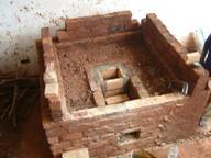
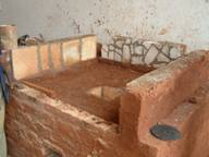
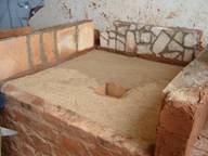
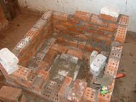
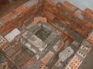
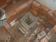
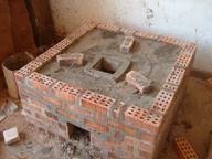
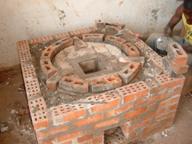
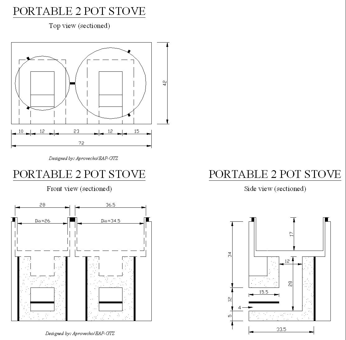
One 2-pot Sunken Rocket
stove with built in skirt.
1.3
Five 200L institutional
stoves were constructed at Musa Body University of Technology. These
stoves, which will be constructed by Kawere Muhammad, were the first of thirty
that were ordered by the UPDF.
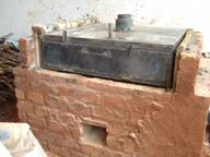
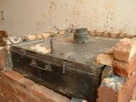
 1.4
1.4
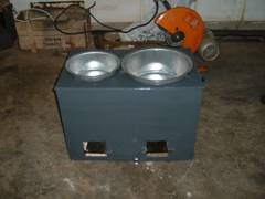
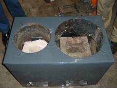
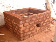
Two 100L portable
metal and insulated brick institutional stoves were constructed. One of
these was an initial prototype constructed at George Sizoomu shop at
Kirinya-Bweyogerere as part of a one-day training. The
second (shown here) was built at Musa’s university of technology in cooperation
with Kawere Muhammad.
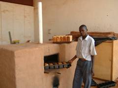
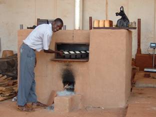
1.5
One 75-loaf bread oven
was designed and constructed. At the end of the contract only cosmetic
finishing touches were necessary for full completion of the oven.
1.5
Before arrival, the
consultant produced plans for a Rocket bread oven that was then built
and tested by GTZ/UIRI.
1.7
Over 50 insulated test
bricks were fired in Cooperation with George Sizoomu and Francis Sebabi at
the Department of Industrial Ceramic / Uganda Polytechnic Kyambogo/
1.8
An adjustable skirt for a
single pot stove was produced by JICA
1.9
Four single pot Rocket
stoves were produced using Vernacular Insulative Ceramic
(VIC).
1.10
One metal mould was
made for firing 30cm by 30 cm by 5cm VIC tiles
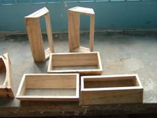
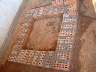
1.11
20 wooden moulds were made for firing the 6
brick VIC stove
2.0 Training
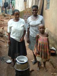
Three women were selected to
use the stoves for a week. GTZ-EAP’s telephone number was given to the selected
women and it was explained that they could contact us toll free at anytime if
they were faced with problems with their demonstration stove.
- One sunken pot stove that was fabricated by
Sizoomu’s artisans; ,
- One VIC rocket stove that was constructed in
March of 2003 in partnership with Kawere Muhammad
- And one Rocket stove that was constructed by the
participants during the NGO training of the previous week
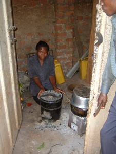
4.0 Household Stove Assessment
(Kasubi,
On
Unfortunately, we were not
able to connect with Frank Ssentongo so we couldn’t plan the visits ahead of
time so we ended up arriving a few days later than scheduled. Although a
surprise visit is a good way of assessing if the stove is being used (Quick!
light the fire, the mzungus are coming!) it is not ideal for eliciting coherent
information from the participants.
4.1
Household #1Betty Mutaisa (tel#077 417 133)
The participant that was
selected during the workshop, Mrs. Mutaisa, was not at home so we interviewed the
maid instead. She seemed a little uncertain, or perhaps a little shy, in
regards to discussing the cooking situation.
 The Rocket stove was not in use when we arrived but
the maid of the house assured us that the stove was being used frequently. She
said that she was only now using charcoal today because she had run out of
wood. Under normal circumstances she said that she would use about 150
shillings worth of wood per day (for approx 8 people) compared to approx. 300
Ush per day for charcoal.
The Rocket stove was not in use when we arrived but
the maid of the house assured us that the stove was being used frequently. She
said that she was only now using charcoal today because she had run out of
wood. Under normal circumstances she said that she would use about 150
shillings worth of wood per day (for approx 8 people) compared to approx. 300
Ush per day for charcoal.
At the end of the visit we
took the stove to a local metal shop to make some adjustments to the skirt and
the pot stand. The stove was then returned to the house.
As mentioned earlier, the women responsible for the stove was not present during our
visit so another visit would be highly recommended.
4.2
Household #2 (Name not available)

 At the second house that we visited the participant
that was selected during the workshop was also not at home but we found the
stove in use outside of the house. It was explained to us that the recipient
was sharing the stove. The woman who was cooking was very pleased with the
stove. In fact when we suggested that we take the stove for the day – to make a
few changes – she appeared very unhappy.
At the second house that we visited the participant
that was selected during the workshop was also not at home but we found the
stove in use outside of the house. It was explained to us that the recipient
was sharing the stove. The woman who was cooking was very pleased with the
stove. In fact when we suggested that we take the stove for the day – to make a
few changes – she appeared very unhappy.
Both the stove and the skirt
were being used. The cook said that she always used the skirt and noted that
food took longer to cook without the skirt. We educated her about the need to
maintain the proper gap between the pot and the skirt. We explained that the
skirt should be no more than the thickness of a pinky finger. (See the Design
Guide for more info on gaps)
She commented that the stove was cooking food
very quickly and saving a considerable amount of fuel - roughly 60-80% less
than the traditional stove. She said that her fuel costs had been reduced from
500 Ush /day to approx 100 Ush/day. This, however, is only when she buys
firewood, which is not everyday). She said that there was nothing that she
would change about the stove and that it was a great to benefit to her family.
4.3
Household #3 Nalongo Jastine Kanyike (telephone # 075 818 334)
This is the only woman who
faced serious problems with her stove. After cooking at her house for a few
days, she was convinced that the stove could not cook traditional foods such as
Matooke. When we went to her house we realized that the stove was still wet
from the mortar. The insulative bricks absorb a lot of moisture during the
construction process and take some time to dry. We explained this to her and
donated some firewood to her for the purpose of drying out the stove.
 A few days later she traveled to UIRI to tell us how
pleased she was about the effectiveness of the stove. It was able to cook a 35
cm diameter saucepan full of Matooke in only 35 minutes. She also said that the
stove was able to cook a large pot of dry unsoaked beans in 2 hours and 45
minutes with only 2 pieces of wood (approx 6cm in diameter by 60cm in length).
She said that this was about 20% of the wood that she would normally use to
accomplish such a task.
A few days later she traveled to UIRI to tell us how
pleased she was about the effectiveness of the stove. It was able to cook a 35
cm diameter saucepan full of Matooke in only 35 minutes. She also said that the
stove was able to cook a large pot of dry unsoaked beans in 2 hours and 45
minutes with only 2 pieces of wood (approx 6cm in diameter by 60cm in length).
She said that this was about 20% of the wood that she would normally use to
accomplish such a task.
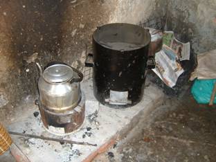
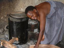
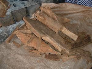
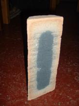
Below is a visual comparison
of the amount of fuel that she used to cook one pot of unsoaked dry beans
before and after the introduction of the single pot sunken rocket stove.
| Before Sunken Pot Rocket Stove | After Sunken Pot Rocket Stove |
 |
 |
On the day of our surprise
visit, when we went to visit her house, we found that she was away on a trip
and that her daughter was in charge of the kitchen. She was using charcoal and
explained that she personally wasn’t using the stove because she didn’t like
having to push in the firewood and that charcoal was much more convenient. This
is not surprising as it would be hard for a wood stove to compete with a
charcoal stove in terms of user convenience, or that her daughter would choose
to use the most expensive method as she was not paying for the fuel.
4.3.1
Perspective
These brief visits suggest
that women who are aware of fuel costs or a faced with severe fuel shortages
due to cost or availability are open to switching from charcoal to wood.
Any commercial cookstove
program should be targeting these people, as they will see the greatest benefit
of the stove.
4.4
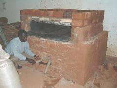
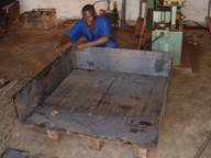
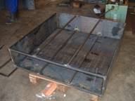
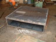
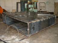
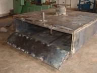
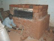
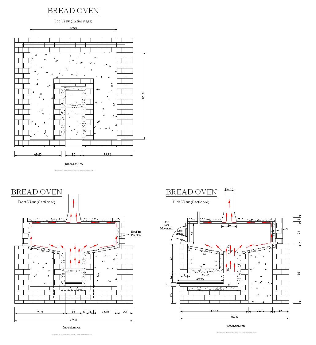
5.0 Rocket Bread Oven
The rocket bread oven
features a 120 cm by 120cm by 30 cm baking compartment made from 2.5 and 1.5 mm
sheet metal. The combustion chamber and the area that encompasses the baking
compartment were constructed with VIC
bricks (see ceramic section for more details) and cut pumice brick.
5.1
The first model was designed
by Peter Scott and built by GTZ and UIRI in May 2003.
UIRI staff tested the bread
oven and found that it was able to cook 17 kg of bread with only 5 kg of dry
wood.
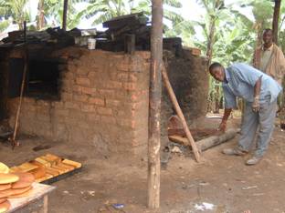 5.2
5.2
This was a considerable
reduction in wood consumption as compared to the traditional wood fired
bread oven that consumed 200 kg to bake the same quantity of bread.
Even though this first
prototype was built around Rocket principles there were a few deviations from
the original design. UIRI staff constructed the combustion chamber before
the final plans arrived so they were forced to improvise some of the
construction details. This led to a couple of small problems that could cause
problems in the long term.
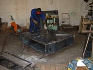
As can be seen from photo
5.1, the area between the combustion chamber and the baking compartment is
blackened with soot. This is a result from fire and smoke spilling out of the
front of the stove. In a properly functioning stove, this area should be free
of soot. (Obviously over time it is possible that careless cooks might allow
fire to occasionally creep out of the front of the stove by leaving it
unattended for long periods of time. This was obviously not the case as the
stove was only fired a few times.
The reason for this
‘back-firing’ was that the gap between the top of the combustion chamber and
the baking compartment was not sufficient. The builders created a 3cm gap
between the bottom, the sides, and the top of the baking compartment. A
3 cm gap along the sides and the top of the compartment is sufficient, but
directly above the combustion chamber, a larger gap is needed (10-15 cm).
5.3
The insufficient 3m gap under the baking chamber leads to
Insufficient air entering
the stove: this creates a ‘lazy’
looking fire in the combustion chamber that creeps back along the fuel and
eventually travels out the front of the stove. In a Rocket Stove with proper
draft the fire is ‘pulled’ up the combustion chamber.
Increased smoke
production The ‘lazy’ fire is a
symbol that the combustion is not at a stochiometric optimum, which means more
smoke is visible out of the chimney. Smoke coming out of a Rocket stove chimney
is a symptom of a incorrectly functioning rocket
stove.
Not surprisingly, both of
these situations were apparent when I observed the stove operating. The fire
crept out of the front of the stove and a large amount of smoke was emitted
from the chimney at the beginning of the fire. Eventually, as the oven heated
up, more draft was created inside the stove, which increased the air flow into
the combustion chamber closer to the stoichiometric rate, which led to a
decrease in smoke production.
One could argue (albeit
erroneously) that the oven eventually functions effectively – smoke production
decreases, the fire is pulled up the chamber and the fire begins to burn more
vigorously.
5.4
This is an incorrect
conclusion for two reasons:
First, the poor combustion
of the initial fire leads to increase soot production. This soot is then
deposited around the baking compartment. This decreases heat transfer and means
that maintenance and cleaning of the baking compartment must be performed more
frequently. Cleaning the oven is time consuming and difficult.
Secondly, placing the
combustion chamber too close to the baking compartment creates a hot spot
directly above the combustion chamber that burns the bread and eventually
degrades the sheet metal.
For this reason, the 2nd
model features a combustion chamber that is 12 cm below the baking compartment
5.5
The 2nd prototype
also features these advantages
- Easier access around the baking compartment for
cleaning
The entire baking compartment is now designed to be removed for
maintenance, alteration and repair without damaging the structure of the oven.
- A hollow pipe connecting the baking compartment
to the external environment to release excess steam.
This pipe connects the
baking compartment to the external environment. This can be opened and closed
by the baker as needed.
- A slightly wider feed chamber (20cm tall by 25
cm wide) to accommodate the larger diameter pieces of wood that are used
by traditional artisans.
- Insulated bricks and whole pumice block are used
to insulate the combustion chamber and around the entire baking
compartment.
The
oven body of the earlier design required more materials.
Multiple
layers of metal, wood ash, and brick were required. Here is a cross section of
the original prototype
|
Brick |
Wood ash |
Metal jacket |
Hot flue gases |
Baking compartment |
Hot flue gases |
Metal jacket |
Wood ash |
Brick |
As
the cross section of the new prototype shows, the new model now only requires
VIC and common brick for insulation. These insulated bricks should last
indefinitely unlike the metal jacket that would have to be replaced
periodically.
|
Brick |
Insulated brick |
Hot flue gases |
Baking compartment |
Hot flue gases |
Insulated brick |
Brick |
If desired, the new design
can also utilize the original brick- wood ash-metal matrix to insulate the
oven.
5.6
Materials used Cost
Approx 350 common bricks 24,500
Approx 10 insulating
bricks/pumice blocks 30,000
Two - 122.5 by 245 cm sheet of 1.5 mm
steel 42,000
One -122.5 by 245 cm sheet
of 2.5 mm steel 70,000
Three 20mm by 1.2 square
pipe 21,000
Angle iron 25 mm by 3 9,000
Chimney 30,000
Fiberglass 15,000
Welding Rods 10,000
Hinges 5,000
Flat bar 7,000
Mica 50,000
Cement 17,500
Vermiculite 2,000
Total Exclusive
of labour 333,000
5.7
5.8
5.9
The way
forward
The
bread oven
I would estimate that there
is sufficient energy within the present combustion chamber to build a double
layer-baking chamber. The existing oven body can be used and in
fact the existing baking compartment can be used, as it only needs to be
extended vertically by 15-30cm or enough to support a second tray of bread. The
top can be cut off, raised up, and supported with three15-30 cm panels attached
to the sides of the oven. Then a second baking door could be fitted on to the
newly extended chamber. Tests should then be run to determine its new baking
capacity.
If the stove is extended
vertically again, I would recommend that the baking compartment be split in two
along the vertical axis, so as to create two baking compartments of equal
volume sitting next to each other(see picture below)
With this layout for the
baking compartments, some modification of the gap between the baking
compartments and the oven body will be necessary.
The cross sectional area gap
(1080cm2) between the baking compartment and the oven body is actually greater
than necessary (see calculating pot gaps in the General design guide
for more info). Because the feed chamber has a perimeter of 90 cm and a cross
sectional area of 500cm2 we actually have more than twice the cross
sectional area than is necessary. If these 3 cm gaps were maintained between
and around the two baking compartments than the cross sectional area would be
greatly increased which would lead to a diminished heat flux to the ovens. For
this reason the gap will have to be narrowed between the baking compartment
(perhaps 1cm wide) and 1.5 cm around the baking compartments
.
This drawing is not to scale but is shown to
give a sense of the proportions between the midpoint and exterior gaps
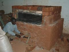
 |
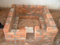
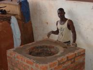
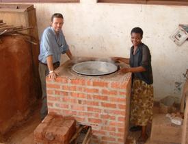
6.0 100L Institutional Brick Rocket Store
 |
 |
| With Chimney | Without Chimney |
Here is the rocket stove maintaining a rolling boil with only a few sticks
This stove was built in
cooperation with Kawere Muhammad and his stove mason Mande.
6.1
Cost
and materials
Kajansi rectangular fire bricks 110,000
Kajansi curved fire bricks 70,000
VIC bricks 30,000
Chimney (optional) 30,000
2 mm top ring and angle iron frame 20,000
Mortar
Cement 17,500
Vermiculite 5,000
Total 285.500Ush*
*This accounting of the
material costs shows that the majority of the cost of the stove (180,000 Ush)
was for the purchase of high-fired Kajansi bricks.
These bricks are valued for
their strength and durability, which is important for those who are building
institutional stoves commercially. However, their cost might put the stove out
of reach for poorer institutions that want to build stoves on their own. These
stoves could be replaced with cheaper local mud bricks. I recommend that
plans be drawn up to substitute cheaper local bricks that cost only 70
shillings each. The total cost for these bricks would be only 13,300USh thus
lowering the cost of the stove by over 166,700 Ush. .
6.2
Mortar For the external (square) body
- a common cement /sand mixture was used.
Common anthill soil/sand mixture could also be used if cement
is not available. Note: This part of the stove will not be exposed to high
temperatures so a special mortar is not necessary
6.3
Mortar For the circular curved brick skirt and combustion chamber
- Four options are available for this mortar:
|
1 part Mica 2 parts high temp clay 1 part low temp clay |
2
parts mica 1
part sand 1
part cement |
2
parts mica 1
part clay |
2
parts sand 1part
true expanded vermiculite 1
part cement |
6.4
Time
to construct
The initial prototype took 3
days to construct but this could most likely be reduced to 2 days
6.5
The
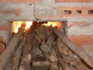
100L institutional brick stove features:
6.6
High heat transfer
efficiency:
The
saucepan is sunken into the stove - only 3 cm (of the 36cm total
saucepan height) is exposed above the edge of the stove.
6.7
Note: Submerging the pot is
extremely important for increasing the surface area exposed to the hot flue
gases and maximizing heat transfer. The sides of this pot (height 35cm /
diameter 63.5) have twice the surface area of the bottom of the saucepan.
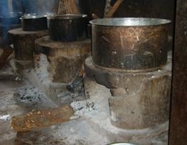
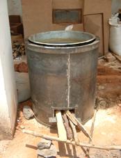
6.8
Only
exposing the bottom of the pot to the hot flue gases (as shown in these
so-called improved stoves from Masindi) decreases heat transfer and over all
efficiency by 50%.

6.9
- An
insulated Rocket Stove combustion chamber.
6.10
The rocket combustion
chamber was constructed with an insulated ceramic brick produced by George
Sizoomu This mixture contains equal parts by weight of Kaolin, stone dust,
sawdust and bowl clay. It is fired at 1300C. This particular mixture, while
effective is more than is actually needed for the Rocket stove. The Rocket
stove does not normally produce temperatures in excess of 900C. Other types of VIC brick or cut pumice
blocks can be used instead.
- Insulation under the pot (with VIC brick)
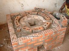
Note the white insulated
bricks that are encircled by the curved (non
insulated) Kajansi Bricks. Ideally these curved bricks would be insulative as
well but strength is a more important consideration than insulation in the
circular bricks
6.11
Stove
Efficiency
The efficiency of the stove
varies depending on how the stove was configured and the type of wood that was
used. (Leonard can you update these
figures?)
|
Stove |
Chimney |
Wood type |
Efficiency |
Time to boil (min) |
|
100 L Brick |
no chimney |
dry wood |
49.5 |
52 |
|
100L Brick |
With chimney |
dry wood |
36% |
58 |
|
100L Brick |
No chimney |
Wet wood |
|
100? |
|
100L Brick |
With chimney |
Wet wood |
|
|
The above table demonstrates
that the chimney decreases efficiency of the stove and that wet wood greatly
decreases the time to boil. It should be noted that, as with all Water Boiling
Tests, no lids were used. Obviously in a real cooking situation, where a lid
should be used, the time to boil would be greatly reduced.
6.12

6.13
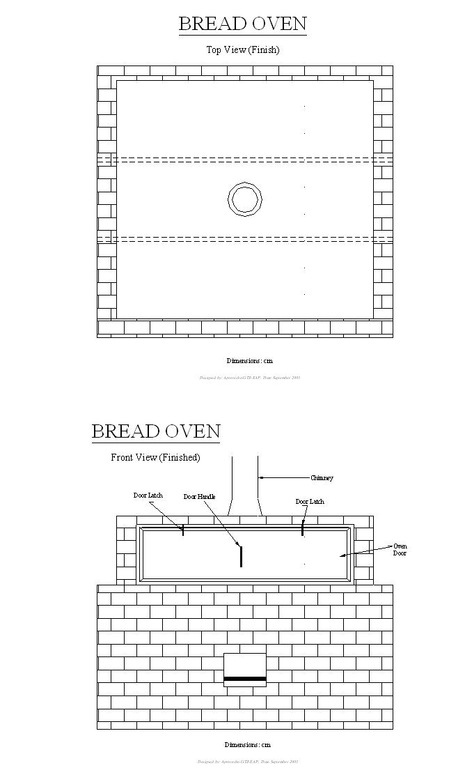
Finishing the 100L
fixed stove
- We need to build the angle iron structure/top
ring around the stove. We have already paid Kawere Muhammad for a properly
sized metal top ring that rests on the brick skirt. We will need to hire
someone to build the angle iron enclosure. I would recommend making it
removable so that we can demonstrate the stove with and without the
chimney.
- Put pot stabilizers in place.
- Repeat tests for dry/wet wood and chimney/no
chimney. Due to the leak in the old pot the stove might still be wet so I
would recommend giving it a good firing to dry it out the day before the
testing. Remember that it is difficult to dry out that brick. Also if you
buy a new pot remember to use it once, to soot it up, before you do tests
on it. Or, conversely, clean it each time you do the test
- More research needs to be done on the insulator
around the skirt. The stove presently has raw sawdust around it. This
should be periodically monitored to see how it responds to the heat of the
bricks. In the future I would recommend using vermiculite where applicable
Once
these tasks are completed, build a prototype in a local school
.
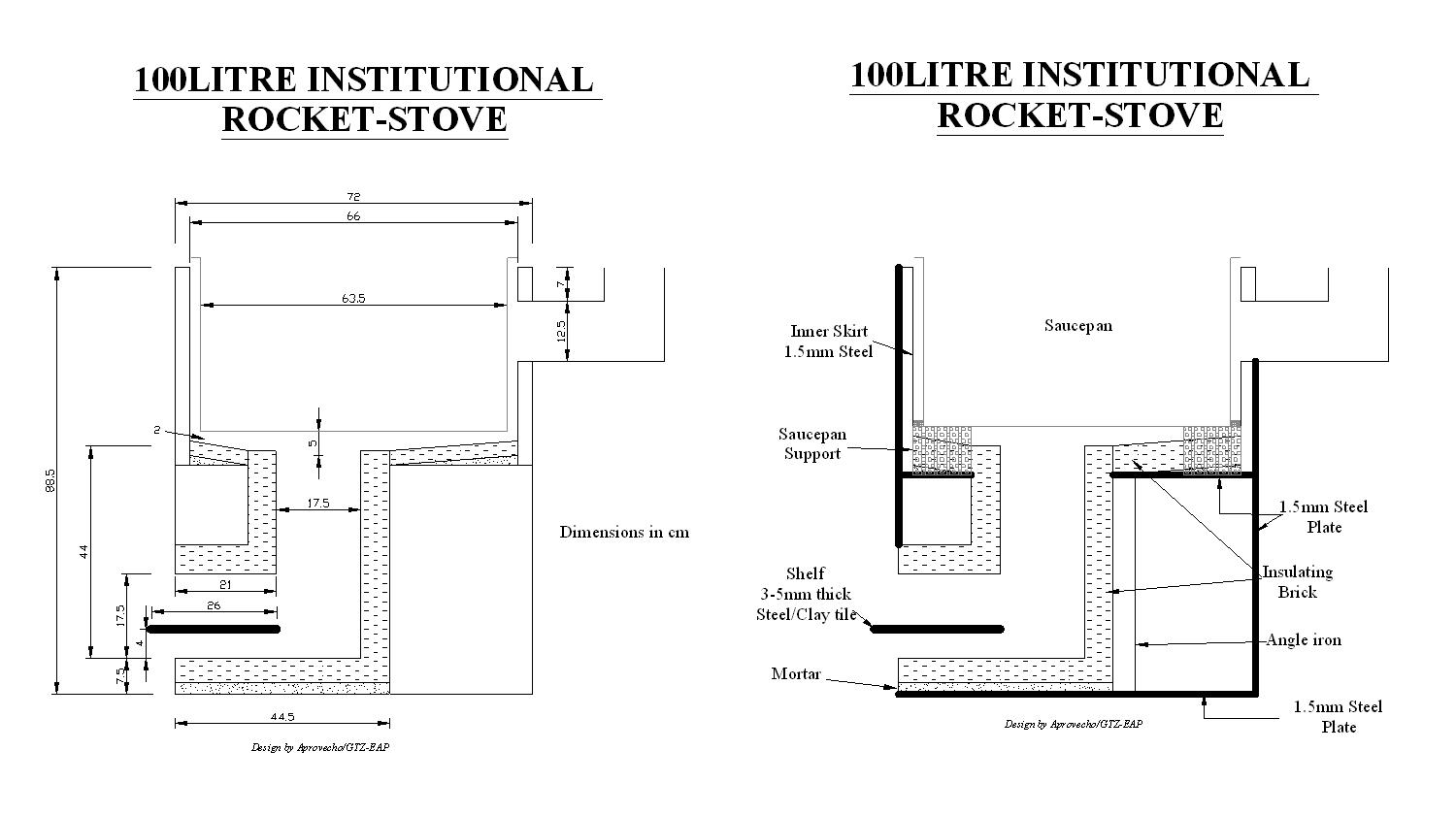
7.0 100L Portable
Institutional Rocket Stove
This stove is built around
the same design as the fixed 100L version. The metal version, however offers an
insulated double walled skirt so higher efficiencies would be expected
7.1
Material cost
One 1225 by 2450mm sheet of
2mm sheet steel 60,000
Two 1225 by 2450mm sheets of
1.5 mm sheet steel 82,000
40 insulated bricks or cut
pumice blocks 40,000
Vermiculite 5,000
45 kg cement
17,000
Tiles (for shelf) 2,000
Angle iron 40mm by 6m 10,000
Cost (excluding labour) 216,000
7.2
Mortar for the combustion
chamber
- Four options are available for this mortar
|
1 part Mica 2 parts high temp clay 1 part low temp clay |
2
parts mica 1
part sand 1
part cement |
2
parts mica 1
part clay |
2
parts sand 1part
true vermiculite 1
part cement |
The area between the bottom
of the saucepan and the stove body is insulated with pumice or VIC bricks. This
increases the heat transfer to the pot and increases the longevity of the stove
(any metal exposed to the hot flue gases or flames is in danger of degradation
7.3
The way forward
The 100L portable institutional
stove
The chimney stove can
achieve higher efficiencies but to do so the gap must be very narrow and
tightly controlled. More research needs to be done on the impact of shrinking
the gap between the pot and the stove body.
See attached
A chimney stove is, by
nature, more difficult to build and maintain. For example, to accommodate the
handles and allow for the easy removal of the saucepan it is necessary to leave
a small gap between the skirt and the saucepan. This means that it is difficult
to completely seal the top of the stove. Cool air can leak through this gap and
this can decrease the effectiveness of the chimney.
8.0
Vernacular Insulated Ceramic
Finding a locally produced
insulated brick is the cornerstone of any Rocket stove program. Attempting to
copy the Rocket stove geometry without following the principles of insulation
will result in a stove that could actually increase wood consumption
compared to traditional or other improved stove designs.
Emphasis must be placed on
locating suitable materials before production of stoves begins in any region.
Otherwise people might adopt the technology and use whatever materials are
available regardless of their suitability.
Some basic points regarding insulating
bricks:
Thin walled, yet higher mass
materials (such as clay tiles) that are surrounded by insulation are acceptable
but not as effective as a combustion chamber that is itself built with
insulating materials (such as the fired sawdust/clay or charcoal/ clay or
vermiculite/clay bricks
Insulation is not just
important for increasing efficiency.
Highly insulated combustion
chambers - as opposed to those only nominally insulated - increase efficiency,
but more importantly, they reduce smoke production in the stove. This is
illustrates by the difference between the three improved LoRocket stoves. The
difference in efficiency between the sawdust stove and the pumice stove is only
approximately 2% but there is a significant reduction in visible smoke (as
noted by Leonard) This focus on combustion is especially important when
building stoves that do not have a chimney. The extra efficiency points that
are noted are a result in an increase in Nominal combustion efficiency and this
will have a profound effect on the users long-term
health.
This contradicts the school
of thought that says its better to build 100,000 stoves at 20% then 30,000
stoves at 33% as the increase will not just increase fuel efficiency but will , more importantly, reduce IAP.
8.1 Material choice
 During the contract period we focused on constructing
charcoal and saw dust bricks (see attached appendix for brick densities and
characteristics). The charcoal bricks were our first material
choice because charcoal fines were thought to be a waste product and they
formed a light and strong brick when fired.
This Charcoal/clay brick (shown here) was artificially dried for 2 days
at 250C and then fired for 24 hours in the electric kiln at 950C. This brick
still has a large portion of charcoal remaining in the brick. The charcoal from
the outer layer of the brick has been burnt away which has created a sufficient
3cm insulative barrier. The remaining charcoal has a low conductivity and
improves the strength of the brick.
During the contract period we focused on constructing
charcoal and saw dust bricks (see attached appendix for brick densities and
characteristics). The charcoal bricks were our first material
choice because charcoal fines were thought to be a waste product and they
formed a light and strong brick when fired.
This Charcoal/clay brick (shown here) was artificially dried for 2 days
at 250C and then fired for 24 hours in the electric kiln at 950C. This brick
still has a large portion of charcoal remaining in the brick. The charcoal from
the outer layer of the brick has been burnt away which has created a sufficient
3cm insulative barrier. The remaining charcoal has a low conductivity and
improves the strength of the brick.
Unfortunately this unburned charcoal clay adds
considerable weight to the brick. It would obviously take a longer period of
time (and more energy) in the kiln to burn all of the charcoal out of the
bricks. More research has to be done on the effectiveness of longer fired charcoal
bricks before they were introduced as a liner into a stove.
The longer firing times,
combined with the extra effort and energy to grind the charcoal into a fine
powder make charcoal bricks a less than perfect option for VIC.
Sifted sawdust bricks – while still
needing more research- seem to offer the best solution in the short term.
I would recommend focusing
on sawdust bricks for the single pot stove and vermiculite bricks for
the institutional stove. The
bricks that we are using in
Some of the test bricks that
we fired in
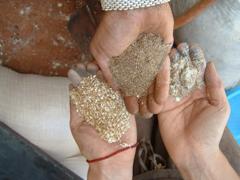
The above photo shows three
different kinds of mica. Starting at bottom left and moving clockwise the
picture shows medium or coarse vermiculite, fine vermiculite and finally
unprocessed mica.
8.2 Design points
- The ideal density of the bricks should be
between .4 and .7 grams/cc.
- Longer drying periods without the use of the
artificial drier will produce a stronger and lighter brick
- All bricks should be dried in the shade for at
least 5 days and then fired in an electric or wood kiln for one day.
Artificial drying is not necessary if sufficient natural drying is
possible.
 |
 |
 |
 |
 |
 |
 |